Okay, there's still a lot of theory to talk about, but before we spend too much time getting bogged down in complex math or difficult concepts, let's get our feet wet with some very basic drawing in OpenGL ES.
If you haven't already done so, grab a copy of
my Empty OpenGL Xcode project template. We'll use this template as a starting point rather than Apple's provided one. You can install it by copying the unzipped folder to this location:
/Developer/Platforms/iPhoneOS.platform/Developer/Library/Xcode/Project Templates/Application/
This template is designed for a full-screen OpenGL application, and has an OpenGL view and a corresponding view controller. The view is designed to be pretty hands-off and you shouldn't need to touch it most of the time. It handles some of the gnarley stuff we'll be talking about later on, like buffer swapping, but it calls out to its controller class for two things.
First, it calls out to the controller once when the view is being setup. The view controller's
setupView: method gets called once to let the controller add any setup work it needs to do. This is where you would set up your viewport, add lights, and do other setup relevant to your project. For today, ignore that method. There's a very basic setup already in place that will let you do simple drawing. Which brings us to the other method.
The controller's
drawView: method will get called at regular intervals based on the value of a constant called
kRenderingFrequency. The initial value of this is
15.0, which means that
drawView: will get called fifteen times a second. If you want to change the rendering frequency, you can find this constant defined in the file called
ConstantsAndMacros.h.
For our first trick, let's add the following code to the existing
drawView: method in
GLViewController.m:
- (void)drawView:(GLView*)view;
{
    Vertex3D    vertex1 = Vertex3DMake(0.0, 1.0, -3.0);
    Vertex3D    vertex2 = Vertex3DMake(1.0, 0.0, -3.0);
    Vertex3D    vertex3 = Vertex3DMake(-1.0, 0.0, -3.0);
    Triangle3D  triangle = Triangle3DMake(vertex1, vertex2, vertex3);

    glLoadIdentity();
    glClearColor(0.7, 0.7, 0.7, 1.0);
    glClear(GL_COLOR_BUFFER_BIT | GL_DEPTH_BUFFER_BIT);
    glEnableClientState(GL_VERTEX_ARRAY);
    glColor4f(1.0, 0.0, 0.0, 1.0);
    glVertexPointer(3, GL_FLOAT, 0, &triangle);
    glDrawArrays(GL_TRIANGLES, 0, 9);
    glDisableClientState(GL_VERTEX_ARRAY);
}
Before we talk about what's going on, go ahead and run it, and you should get something that looks like this:
It's a simple method; you could probably figure out what's going on if you try, but let's walk through it together. Since our method draws a triangle, we need three vertices, so we create three of those
Vertex3D objects we talked about in the
previous posting in this series:
    Vertex3D    vertex1 = Vertex3DMake(0.0, 1.0, -3.0);
    Vertex3D    vertex2 = Vertex3DMake(1.0, 0.0, -3.0);
    Vertex3D    vertex3 = Vertex3DMake(-1.0, 0.0, -3.0);
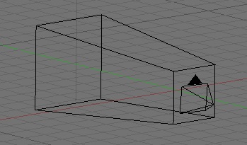
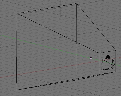
You should notice that the z value for all three vertices is the same, and that that value (-3.0) is "behind" the origin. Because we haven't done anything to change it, we're looking into our virtual world as if we were standing on the origin, which is the default starting location. By placing the triangle at a z-position of -3, we ensure that we can see it on the screen.
After that, we create a
Triangle3D object made up of those three vertices.
Triangle3D triangle = Triangle3DMake(vertex1, vertex2, vertex3);
Now, that's pretty easy code to understand, right? But, behind the scenes, what it looks like to the computer is an array of 9
GLfloats. We could have accomplished the same thing by doing this:
GLfloat triangle[] = {0.0, 1.0, -3.0, 1.0, 0.0, -3.0, -1.0, 0.0, -3.0};Well, not quite exactly the same thing - there's one very minor but important difference. In our first example, we have to pass the address of our
Triangle3D object into OpenGL (e.g.
&triangle), but in the second example using the array, we'd simply pass in the array, because C arrays are pointers. But, don't worry too much about that, because this example will be the last time we declare a
Triangle3D object this way. I'll explain why in a moment, but let's finish going through our code. The next thing we do is load the identity matrix. I'll devote at least one whole posting to transformation matrices, what they are and how they are used, but just think of this call as a "reset button" for OpenGL. It gets rid of any rotations, movement, or other changes to the virtual world and puts us back at the origin standing upright.
glLoadIdentity();
After that, we tell OpenGL that all drawing should be done over a light grey background. OpenGL generally expects colors to be defined using four clamped values. Remember from the previous post, clamped floats are floating point values that run from 0.0 to 1.0. So, we define colors by their red, green, and blue components, along with another component called alpha, which defines how much of what's behind the color shows through. Don't worry about alpha for now - for the time being, we'll just always set alpha to 1.0, which defines an opaque color.
    glClearColor(0.7, 0.7, 0.7, 1.0);
    glClear(GL_COLOR_BUFFER_BIT | GL_DEPTH_BUFFER_BIT);
To define white in OpenGL, we'd pass 1.0 for all four components. To define an opaque black, we'd pass 0.0 for the red, green, and blue components and 1.0 for alpha. The second line of code in that last example is the one that actually tells OpenGL to clear out anything that's been drawn before and erases everything to the clear color.
You're probably wondering what the two arguments to the
glClear() call are. Well, again, we don't want to get too far ahead of ourselves, but those are constants that refer to values stored in a bitfield. OpenGL maintains a number of
buffers, which are just chunks of memory used for different aspects of drawing. By logical or'ing these two particular values together, we tell OpenGL to clear two different buffers - the
color buffer and the
depth buffer. The color buffer stores the color for each pixel of the current frame. This is basically what you see on the screen. The depth buffer (sometimes also called the "z-buffer") holds information about how close or near the viewer each potential pixel is. It uses this information to determine whether a pixel needs to be drawn or not. Those are the two buffers you'll see most often in OpenGL. There are others, such as the stencil buffer and the accumulation buffer, but we're not going to talk about those, at least for a while. For now, just remember that before you draw a frame, you need to clear these two buffers so that the previous contents doesn't mess things up for you.
After that, we enable one of OpenGL's features called
vertex arrays. This feature could probably just be turned on once in the
setupView: method, but as a general rule, I like to enable and disable the functionality I use. You never know when another piece of code might be doing things differently. if you turn what you need on and then off again, the chances of problems are greatly reduced. In this example, say we had another class that didn't use vertex arrays to draw, but used vertex buffer objects instead. If either of the chunks of code left something enabled or didn't explicitly enable something they needed, one or both of the methods could end up with unexpected results.
glEnableClientState(GL_VERTEX_ARRAY);
The next thing we do is set the color that we're going to draw in. This line of code sets the drawing color to a bright red.
glColor4f(1.0, 0.0, 0.0, 1.0);
Now, all drawing done until another call to
glColor4f() will be done using the color red. There are some exceptions to that, such as code that draws a textured shape, but basically, setting the color like this sets the color for all calls that follow it.
Since we're drawing with vertex arrays, we have to tell OpenGL where the array of vertices is. Remember, an array of vertices is just a C array of
GLfloats, with each set of three values representing one vertex. We created a
Triangle3D object, but in memory, it's exactly the same as nine consecutive
GLfloats, so we can just pass in the address of the
triangle.
glVertexPointer(3, GL_FLOAT, 0, &triangle);
The first parameter to
glVertexPointer() indicates how many
GLfloats represent each vertex. You can pass either 2 or 3 here depending on whether you're doing two-dimensional or three-dimensional drawing. Even though our object exists in a plane, we're drawing it in a three-dimensional virtual world and have defined it using three values per vertex, so we pass in
3 here. Next, we pass in an
enum that tells OpenGL that our vertices are made up of
GLfloats. They don't have to be - OpenGL ES is quite happy to let you use most any datatype in a vertex array, but it's rare to see anything other than
GL_FLOAT. The next parameter... well, don't worry about the next parameter. That's a topic for future discussion. For now, it will always, always, always be
0. In a future posting, I'll show you how to use this parameter to interleave different types of data about the same object into a single data structure, but that's heavier juju than I'm ready to talk about now.
After that, we tell OpenGL to draw triangles between the vertices in the array we previously submitted.
glDrawArrays(GL_TRIANGLES, 0, 9);
As you probably guessed, the first parameter is an
enum that tells OpenGL what to draw. Although OpenGL ES doesn't support quads or any other polygon besides triangles, it does still support a variety of drawing modes, including the ability do draw points, lines, line loops, triangle strips, and triangle fans. We'll talk about the various drawing modes later. For now, let's just stick with triangles.
Finally, we disable the one feature that we enabled earlier so we don't mess up other code elsewhere. Again, there is no other code in this example, but usually when you're using OpenGL, drawing is potentially happening from multiple objects.
glDisableClientState(GL_VERTEX_ARRAY);
And that's it. It works. It's not very impressive, and it's not very efficient, but it works. You're drawing in OpenGL. Yay! A certain number of times every second, this method is getting called, and it's drawing. Don't believe me? Add the following bold code to the method and run it again:
- (void)drawView:(GLView*)view;
{
    static      GLfloat rotation = 0.0;

    Vertex3D    vertex1 = Vertex3DMake(0.0, 1.0, -3.0);
    Vertex3D    vertex2 = Vertex3DMake(1.0, 0.0, -3.0);
    Vertex3D    vertex3 = Vertex3DMake(-1.0, 0.0, -3.0);
    Triangle3D  triangle = Triangle3DMake(vertex1, vertex2, vertex3);

    glLoadIdentity();
    glRotatef(rotation, 0.0, 0.0, 1.0);
    glClearColor(0.7, 0.7, 0.7, 1.0);
    glClear(GL_COLOR_BUFFER_BIT | GL_DEPTH_BUFFER_BIT);
    glEnableClientState(GL_VERTEX_ARRAY);
    glColor4f(1.0, 0.0, 0.0, 1.0);
    glVertexPointer(3, GL_FLOAT, 0, &triangle);
    glDrawArrays(GL_TRIANGLES, 0, 9);
    glDisableClientState(GL_VERTEX_ARRAY);

    rotation+= 0.5;
}
When you run it again, the triangle should slowly revolve around the origin. Don't worry too much about the mechanics of rotation, I just wanted to show you that your drawing code was getting called many times a second.
What if we want to draw a square? Well, OpenGL ES doesn't have squares, so we have to define a square out of triangles. That's easy enough to do - a square can be created out of two right triangles. How do we tweak the code above to draw two triangles, rather than one? Can we create two
Triangle3Ds and submit those? Well, yeah, we could. But that would be inefficient. It would be better if we submitted both triangles as part of the same vertex array. We can do that by declaring an array of
Triangle3D objects, or by allocating a chunk of memory that happens to be the same size as two
Triangle3Ds or eighteen
GLfloats.
Here's one way:
- (void)drawView:(GLView*)view;
{
    Triangle3D  triangle[2];
    triangle[0].v1 = Vertex3DMake(0.0, 1.0, -3.0);
    triangle[0].v2 = Vertex3DMake(1.0, 0.0, -3.0);
    triangle[0].v3 = Vertex3DMake(-1.0, 0.0, -3.0);
    triangle[1].v1 = Vertex3DMake(-1.0, 0.0, -3.0);
    triangle[1].v2 = Vertex3DMake(1.0, 0.0, -3.0);
    triangle[1].v3 = Vertex3DMake(0.0, -1.0, -3.0);

    glLoadIdentity();
    glClearColor(0.7, 0.7, 0.7, 1.0);
    glClear(GL_COLOR_BUFFER_BIT | GL_DEPTH_BUFFER_BIT);
    glEnableClientState(GL_VERTEX_ARRAY);
    glColor4f(1.0, 0.0, 0.0, 1.0);
    glVertexPointer(3, GL_FLOAT, 0, &triangle);
    glDrawArrays(GL_TRIANGLES, 0, 18);
    glDisableClientState(GL_VERTEX_ARRAY);
}
Run it now, and you should get something like this:
That code is less than ideal, however, because we're allocating our geometry on the stack, and we're causing a additional memory to be used because our
Vertex3DMake() method creates a new
Vertex3D on the stack, and then copies the values into the array.
For a simple example like this, that works fine, but in more complex cases, the geometry for defining 3D objects will be large enough that you don't want to be allocating it on the stack and you don't want to be allocating memory more than once for a given vertex, so it's a good idea to get in the habit of allocating your vertices on the heap by using our old friend
malloc() (although I sometimes like to use
calloc() instead because by setting all the values to zero, some errors are easier to track down). First, we need a function to set the values of an existing vertex instead of creating a new one the way
Vertex3DMake() does. This'll work:
static inline void Vertex3DSet(Vertex3D *vertex, CGFloat inX, CGFloat inY, CGFloat inZ)
{
    vertex->x = inX;
    vertex->y = inY;
    vertex->z = inZ;
}
Now, here's the exact same code re-written to allocate the two triangles on the heap using this new function:
- (void)drawView:(GLView*)view;
{
    Triangle3D  *triangles = malloc(sizeof(Triangle3D) * 2);

    Vertex3DSet(&triangles[0].v1, 0.0, 1.0, -3.0);
    Vertex3DSet(&triangles[0].v2, 1.0, 0.0, -3.0);
    Vertex3DSet(&triangles[0].v3, -1.0, 0.0, -3.0);
    Vertex3DSet(&triangles[1].v1, -1.0, 0.0, -3.0);
    Vertex3DSet(&triangles[1].v2, 1.0, 0.0, -3.0);
    Vertex3DSet(&triangles[1].v3, 0.0, -1.0, -3.0);

    glLoadIdentity();
    glClearColor(0.7, 0.7, 0.7, 1.0);
    glClear(GL_COLOR_BUFFER_BIT | GL_DEPTH_BUFFER_BIT);
    glEnableClientState(GL_VERTEX_ARRAY);
    glColor4f(1.0, 0.0, 0.0, 1.0);
    glVertexPointer(3, GL_FLOAT, 0, triangles);
    glDrawArrays(GL_TRIANGLES, 0, 18);
    glDisableClientState(GL_VERTEX_ARRAY);

    if (triangles != NULL)
        free(triangles);
}
Okay, we've covered a lot of ground, but let's got a little further. Remember how I said that OpenGL ES has more than one drawing mode? Well, this square shape that currently requires 6 vertices (18
GLfloats) to draw can actually be drawn with just four vertices (12
GLfloats) using the drawing mode known as
triangle strips (
GL_TRIANGLE_STRIP).
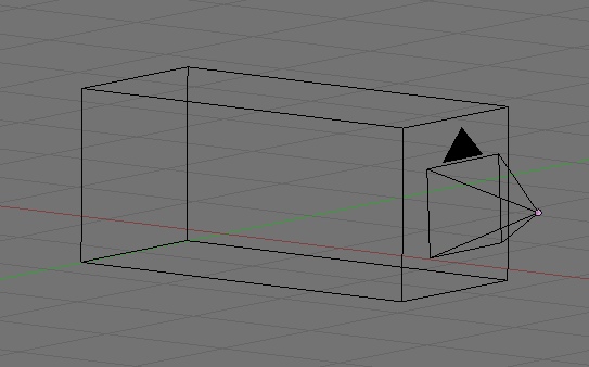
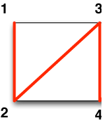
Here's the basic idea behind a triangle strip: the first triangle in the strip is made up of the first three vertices (indexes 0, 1, 2). The second triangle is made up of two of the vertices from the previous triangle along with the next vertex in the array, and so on through the array. This picture might make more sense - the first triangle is vertices 1, 2, 3, the next is vertices 2, 3, 4, etc.:

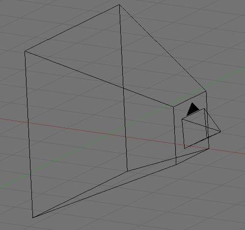
So, our square can be made like this:
The code to do it this way, looks like this:
- (void)drawView:(GLView*)view;
{
    Vertex3D  *vertices = malloc(sizeof(Vertex3D) * 4);

    Vertex3DSet(&vertices[0], 0.0, 1.0, -3.0);
    Vertex3DSet(&vertices[1], 1.0, 0.0, -3.0);
    Vertex3DSet(&vertices[2], -1.0, 0.0, -3.0);
    Vertex3DSet(&vertices[3], 0.0, -1.0, -3.0);

    glLoadIdentity();

    glClearColor(0.7, 0.7, 0.7, 1.0);
    glClear(GL_COLOR_BUFFER_BIT | GL_DEPTH_BUFFER_BIT);
    glEnableClientState(GL_VERTEX_ARRAY);
    glColor4f(1.0, 0.0, 0.0, 1.0);
    glVertexPointer(3, GL_FLOAT, 0, vertices);
    glDrawArrays(GL_TRIANGLE_STRIP, 0, 12);
    glDisableClientState(GL_VERTEX_ARRAY);

    if (vertices != NULL)
        free(vertices);
}
Let's go to the first code sample to see something. Remember how we drew that first triangle? We used
glColor4f() to set a color and said that it would set the color for all calls that follow. That means that every object defined in a vertex array has to be drawn in the same color? What? That's pretty limiting, isn't it?
Well, no. Just as OpenGL ES will allow you to pass vertices all at once in an array, it will also let you pass in a
color array to specify the color to be used for each vertex. If you choose to use a color array, you need to have one color (four
GLfloats) for each vertex. Color arrays have to be turned on using
glEnableClientState(GL_COLOR_ARRAY);
Otherwise, the process is basically the same as passing in vertex arrays. We can use the same trick be defining a
Color3D struct that contains four
GLfloat members. Here's how you could pass in a different color for each array of that original triangle we drew:
- (void)drawView:(GLView*)view;
{
    Vertex3D    vertex1 = Vertex3DMake(0.0, 1.0, -3.0);
    Vertex3D    vertex2 = Vertex3DMake(1.0, 0.0, -3.0);
    Vertex3D    vertex3 = Vertex3DMake(-1.0, 0.0, -3.0);
    Triangle3D  triangle = Triangle3DMake(vertex1, vertex2, vertex3);

    Color3D     *colors = malloc(sizeof(Color3D) * 3);
    Color3DSet(&colors[0], 1.0, 0.0, 0.0, 1.0);
    Color3DSet(&colors[1], 0.0, 1.0, 0.0, 1.0);
    Color3DSet(&colors[2], 0.0, 0.0, 1.0, 1.0);

    glLoadIdentity();
    glClearColor(0.7, 0.7, 0.7, 1.0);
    glClear(GL_COLOR_BUFFER_BIT | GL_DEPTH_BUFFER_BIT);
    glEnableClientState(GL_VERTEX_ARRAY);
    glEnableClientState(GL_COLOR_ARRAY);
    glColor4f(1.0, 0.0, 0.0, 1.0);
    glVertexPointer(3, GL_FLOAT, 0, &triangle);
    glColorPointer(4, GL_FLOAT, 0, colors);
    glDrawArrays(GL_TRIANGLES, 0, 9);
    glDisableClientState(GL_VERTEX_ARRAY);
    glDisableClientState(GL_COLOR_ARRAY);

    if (colors != NULL)
        free(colors);
}
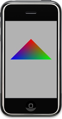
If you run that, it should create a triangle that looks like this:
Let's look at one more thing today. One problem with the way we've been doing things is that if a vertex is used more than once (except in conjoining triangles in a triangle strip or triangle fan), you have to pass the same vertex into OpenGL multiple times. That's not a big deal, but you generally want to minimize the amount of data you're pushing into OpenGL, so pushing the same 4-byte floating point value over and over is less than ideal. In some meshes, a vertex could conceivably be used in seven or more different triangles, so your vertex array could be many times larger than it needs to be.
When dealing with these complex geometries, there's a way to avoid sending the same vertex multiple times, and it's by using something called
elements to refer to vertices by their index in the vertex array. How this works is you'd create a vertex array that has each vertex once and only once. Then, you'd create another array of integers using the smallest unsigned integer datatype that will hold the number of unique vertices you have. In other words, if your vertex array has less than 256 vertices, then you would create an array of
GLubytes, if it's more than 256, but less than 65,536, use
GLushort. You build your triangles (or other shape) in this second array by referring to the vertices in the first array by their index. So, if you create vertices array with 12 vertices, then you refer to the first vertex in the array, you refer to as
0. You submit your vertices exactly the same way you did before, but instead of calling
glDrawArrays(), you call a different function called
glDrawElements() and pass in the integer array.
Let's finish our tutorial with a real, honest-to-goodness 3D shape: an icosahedron. Everybody else does cubes, but we're going to be geeky and do a twenty-sided die (sans numbers). Replace
drawView: with this new version:
- (void)drawView:(GLView*)view;
{
static GLfloat rot = 0.0;
static const Vertex3D vertices[]= {
{0, -0.525731, 0.850651}, {0.850651, 0, 0.525731}, {0.850651, 0, -0.525731}, {-0.850651, 0, -0.525731}, {-0.850651, 0, 0.525731}, {-0.525731, 0.850651, 0}, {0.525731, 0.850651, 0}, {0.525731, -0.850651, 0}, {-0.525731, -0.850651, 0}, {0, -0.525731, -0.850651}, {0, 0.525731, -0.850651}, {0, 0.525731, 0.850651} };
    static const Color3D colors[] = {
         {1.0, 0.0, 0.0, 1.0},
         {1.0, 0.5, 0.0, 1.0},
         {1.0, 1.0, 0.0, 1.0},
         {0.5, 1.0, 0.0, 1.0},
         {0.0, 1.0, 0.0, 1.0},
         {0.0, 1.0, 0.5, 1.0},
         {0.0, 1.0, 1.0, 1.0},
         {0.0, 0.5, 1.0, 1.0},
         {0.0, 0.0, 1.0, 1.0},
         {0.5, 0.0, 1.0, 1.0},
         {1.0, 0.0, 1.0, 1.0},
         {1.0, 0.0, 0.5, 1.0}
    };
    static const GLubyte icosahedronFaces[] = {
        1, 2, 6,
        1, 7, 2,
        3, 4, 5,
        4, 3, 8,
        6, 5, 11,
        5, 6, 10,
        9, 10, 2,
        10, 9, 3,
        7, 8, 9,
        8, 7, 0,
        11, 0, 1,
        0, 11, 4,
        6, 2, 10,
        1, 6, 11,
        3, 5, 10,
        5, 4, 11,
        2, 7, 9,
        7, 1, 0,
        3, 9, 8,
        4, 8, 0,
    };
glLoadIdentity();
glTranslatef(0.0f,0.0f,-3.0f);
glRotatef(rot,1.0f,1.0f,1.0f);
glClearColor(0.7, 0.7, 0.7, 1.0);
glClear(GL_COLOR_BUFFER_BIT | GL_DEPTH_BUFFER_BIT);
glEnableClientState(GL_VERTEX_ARRAY);
glEnableClientState(GL_COLOR_ARRAY);
glVertexPointer(3, GL_FLOAT, 0, vertices);
glColorPointer(4, GL_FLOAT, 0, colors);
glDrawElements(GL_TRIANGLES, 60, GL_UNSIGNED_BYTE, icosahedronFaces);
glDisableClientState(GL_VERTEX_ARRAY);
glDisableClientState(GL_COLOR_ARRAY);
static NSTimeInterval lastDrawTime;
if (lastDrawTime)
{
NSTimeInterval timeSinceLastDraw = [NSDate timeIntervalSinceReferenceDate] - lastDrawTime;
rot+=50 * timeSinceLastDraw;
}
lastDrawTime = [NSDate timeIntervalSinceReferenceDate];
}
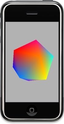
Before we talk about what's going on, let's run it and see the pretty shape spin:
It's not completely 3D looking because there are no lights and even if we had lights, we haven't told OpenGL what it needs to know to calculate how light should reflect off of our shape (that's a topic for a future posting - but if you want to, you can read some existing posts on the topic
here and
here).
So, what did we do here? First, we created a static variable to track the rotation of the object.
static GLfloat rot = 0.0;
Then we defined our vertex array. We did it a little differently than before, but the result is the same. Since our geometry is not changing at all, we can make it
const rather than allocating and deallocating memory every frame, and provide the values between curley braces:
static const Vertex3D vertices[]= {
{0, -0.525731, 0.850651}, {0.850651, 0, 0.525731}, {0.850651, 0, -0.525731}, {-0.850651, 0, -0.525731}, {-0.850651, 0, 0.525731}, {-0.525731, 0.850651, 0}, {0.525731, 0.850651, 0}, {0.525731, -0.850651, 0}, {-0.525731, -0.850651, 0}, {0, -0.525731, -0.850651}, {0, 0.525731, -0.850651}, {0, 0.525731, 0.850651} };Then we create a color array the same way. This creates an array of
Color3D objects, one for each of the vertices in the previous array:
static const Color3D colors[] = {
{1.0, 0.0, 0.0, 1.0},
{1.0, 0.5, 0.0, 1.0},
{1.0, 1.0, 0.0, 1.0},
{0.5, 1.0, 0.0, 1.0},
{0.0, 1.0, 0.0, 1.0},
{0.0, 1.0, 0.5, 1.0},
{0.0, 1.0, 1.0, 1.0},
{0.0, 0.5, 1.0, 1.0},
{0.0, 0.0, 1.0, 1.0},
{0.5, 0.0, 1.0, 1.0},
{1.0, 0.0, 1.0, 1.0},
{1.0, 0.0, 0.5, 1.0}
};Finally, we create the array that actually defines the shape of the icosahedron. Those twelve vertices above, by themselves, don't describe this shape. OpenGL needs to know how to connect them, so for that, we create an array of integers (in this case
GLubytes) that point to the vertices that make up each triangle.
static const GLubyte icosahedronFaces[] = {
1, 2, 6,
1, 7, 2,
3, 4, 5,
4, 3, 8,
6, 5, 11,
5, 6, 10,
9, 10, 2,
10, 9, 3,
7, 8, 9,
8, 7, 0,
11, 0, 1,
0, 11, 4,
6, 2, 10,
1, 6, 11,
3, 5, 10,
5, 4, 11,
2, 7, 9,
7, 1, 0,
3, 9, 8,
4, 8, 0,
};So, the first three numbers in
icosahedronFaces are 1,2,6, which means to draw a triangle between the vertices at indices 1 (
0.850651, 0, 0.525731), 2 (
0.850651, 0, 0.525731), and 6 (
0.525731, 0.850651, 0).
The next chunk is nothing new, we just load the identity matrix (reset all transformations), move the shape away from the camera and rotate it, set the background color, clear the buffers, enable vertex and color arrays, then feed OpenGL our vertex array. All that is just like in some of the earlier examples.
    glLoadIdentity();
    glTranslatef(0.0f,0.0f,-3.0f);
    glRotatef(rot,1.0f,1.0f,1.0f);
    glClearColor(0.7, 0.7, 0.7, 1.0);
    glClear(GL_COLOR_BUFFER_BIT | GL_DEPTH_BUFFER_BIT);
    glEnableClientState(GL_VERTEX_ARRAY);
    glEnableClientState(GL_COLOR_ARRAY);
    glColor4f(1.0, 0.0, 0.0, 1.0);
    glVertexPointer(3, GL_FLOAT, 0, vertices);
    glColorPointer(4, GL_FLOAT, 0, colors);
But, then, we don't draw
glDrawArrays(). We call
glDrawElements():
glDrawElements(GL_TRIANGLES, 60, GL_UNSIGNED_BYTE, icosahedronFaces);
After that, we just disable everything, and then increment the rotation variable based on how much time has elapsed since the last frame was drawn:
    glDisableClientState(GL_VERTEX_ARRAY);
    glDisableClientState(GL_COLOR_ARRAY);
    static NSTimeInterval lastDrawTime;
    if (lastDrawTime)
    {
        NSTimeInterval timeSinceLastDraw = [NSDate timeIntervalSinceReferenceDate] - lastDrawTime;
        rot+=50 * timeSinceLastDraw;
    }
    lastDrawTime = [NSDate timeIntervalSinceReferenceDate];
So, remember: if you provide the vertices in the right order to be drawn, you use
glDrawArrays(), but if you provide an array of vertices and then a separate array of indices to identify the order they need to be drawn in, then you use
glDrawElements().
Okay, that's enough for today. I covered a lot more ground than I intended to, and I probably got ahead of myself here, but hopefully this was helpful. In the next installment, we go back to conceptual stuff.
Please feel free to play with the drawing code, add more polygons, change colors, etc. There's a lot more to drawing in OpenGL than we covered here, but you've now seen the basic idea behind drawing 3D objects on the iPhone: You create a chunk of memory to hold all the vertices, pass the vertex array into OpenGL, and then tell it to draw those vertices.
 3:08 PM
 Unknown

 Posted in: WWDC